Choosing a distance sensor for a moving target starts with the motion, not the sensor. Define the target's speed, direction and how long it stays in the measurement zone; then verify that the sensor's response time and output rate are short compared with that window, that its repeatability meets the positioning tolerance, and that the target's surface and angle return a usable signal. Range, interface and mounting are confirmed last.
Key Takeaways
- Motion first, sensor second. Target speed, travel direction and time-in-zone determine the required response time and update rate before any model is discussed.
- Repeatability is the working number for positioning. Accuracy tells you how true a reading is; repeatability tells you how consistently the sensor reproduces it — and positioning tasks live on consistency.
- Target angle and surface move the effective specification. A tilted, glossy or dark target reduces returned signal; the published figures assume favorable conditions.
- The interface must carry the speed. A fast sensor behind a slow polled interface delivers slow data. Check the whole chain: sensor response, output update, controller input cycle.
- Verify by test at maximum line speed. Published values are model-specific and measured under defined conditions; a sample test on the real target at real speed is the final gate.
Step 1 — Characterize the Motion Before the Sensor
Write down four motion facts before opening any catalog:
- Target speed and direction. Lateral (crossing the beam), axial (approaching/receding) or both. Axial motion stresses measurement rate; lateral motion stresses response time and spot size.
- Time in the measurement zone. How long the target is available to measure. A target crossing a 20 mm zone at 1 m/s is measurable for about 20 ms — every element of the measurement chain must fit inside that window with margin.
- Positioning tolerance. The repeatability the application actually needs — not "as good as possible," but the number the machine design requires.
- Measurement cadence. Continuous tracking (closed-loop positioning) or single-shot capture (verify position, then act). Continuous tracking needs a high sustained update rate; single-shot needs a fast, repeatable response.
Step 2 — Match Response Time and Update Rate to the Speed
Two different specifications control whether a sensor keeps up with a moving target, and confusing them is the most common selection error:
- Response time — how quickly the sensor reacts to a step change in distance. It bounds how fast a lateral target event can be registered.
- Update rate / measurement frequency — how many independent readings per second the sensor delivers. It bounds how finely an axial motion is tracked and how quickly a controller sees fresh data.
The engineering rule: the sensor's response time should be well inside the target's time-in-zone, and the update rate should deliver several readings across the tolerance band you are controlling to. As a concrete, manufacturer-stated reference point, the KJT Sensors TLS-30C laser distance sensor publishes an output time from ≥4 ms with selectable measurement frequencies of 5, 10, 20 and 30 Hz, plus a settable sliding average (fast/slow) that trades responsiveness against noise smoothing. Whether those figures suit your application depends on the motion facts from Step 1 — a 30 Hz stream delivers a reading every ~33 ms, which suits positioning tasks at moderate speeds but not high-speed event capture. For radar-based moving-target work, KJT Sensors publishes millisecond-level response on its radar family, and radar additionally measures target speed directly.
Interface check: the fastest sensor is only as fast as its slowest link. Analog outputs update continuously but must be sampled by the controller; RS485 delivers digital values at the bus's polling cadence; switching outputs (PNP/NPN or relay) answer "in position / not in position" with the sensor's response time. Define where the speed decision is made — inside the sensor (switching threshold, e.g. the TLS-30C's Distance-Object mode) or in the controller (continuous data) — and size the interface accordingly.
Step 3 — Specify Repeatability, Then Accuracy
For moving-target positioning, specify in this order:
- Repeatability — the spread of readings on the same target under the same conditions. This is the number that decides whether your machine can return to a position reliably.
- Resolution — the smallest distance increment the sensor reports (the TLS-30C publishes 1 mm).
- Accuracy — how close the reading is to the true distance (the TLS-30C publishes 1.5 mm + 0.5‰ of distance).
A note on evidence discipline: repeatability is often stated under defined statistical conditions (the TLS-30C page notes a 1σ basis) and varies with averaging settings, target surface and distance. If the published material for your candidate model does not state repeatability for your operating point, treat that as an open question for the manufacturer's application engineer — and settle it with a sample test, not an assumption.
Step 4 — Qualify the Target and the Installation
- Surface and color. Dark, glossy or transparent targets return less light for optical sensors. The TLS family states detection of vertical or tilted targets regardless of color, material or gloss, but extreme surfaces still reduce effective range and stability — verify on the real target. If readings on dark or glossy targets are unstable in an existing installation, that is a troubleshooting case .
- Target angle. A tilted target deflects the reflected beam; keep the sensor axis near-perpendicular to the measured surface, or confirm performance at the actual angle.
- Spot size versus target size. The measurement spot must stay on the target across the whole motion. The TLS-30C publishes a 15 × 15 mm spot at 10 m — at longer ranges the spot grows, and small or edge-crossing targets need this checked.
- Vibration and mounting. A moving machine shakes its sensors. Rigid brackets, short cantilevers and vibration-rated mounting preserve repeatability; the mechanical layer is part of the measurement specification.
- Environment. Dust, steam and ambient light consume optical signal margin; the TLS-30C publishes an industrial enclosure with high ambient-light immunity, while radar is the fallback for optically hostile air. See the laser-vs-radar-vs-ultrasonic comparison for the environment-driven technology decision.
Moving-Target Application-Data Checklist
This checklist is the original working tool of the article — complete it before requesting a model recommendation:
| # | Data item | Why it is needed |
|---|---|---|
| 1 | Target speed (max/typical) and direction of motion | Sizes response time and update rate |
| 2 | Time the target is in the measurement zone | Bounds the total measurement chain |
| 3 | Positioning tolerance (repeatability requirement) | Selects the performance class |
| 4 | Measuring range and standoff distance | Selects the range class (KJT TLS family publishes classes from 1 m to 200 m) |
| 5 | Target material, color, surface, transparency | Confirms returned-signal adequacy |
| 6 | Target size versus measurement spot at working distance | Prevents edge and overshoot errors |
| 7 | Mounting position, vibration, available space | Mechanical stability and alignment |
| 8 | Environment: dust, steam, ambient light, temperature | Technology and enclosure selection |
| 9 | Required output: switching / analog / RS485 and decision location | Interface and system architecture |
| 10 | Decision cadence: continuous tracking or single-shot | Update-rate sizing |
KJT Sensors Options for Moving Targets
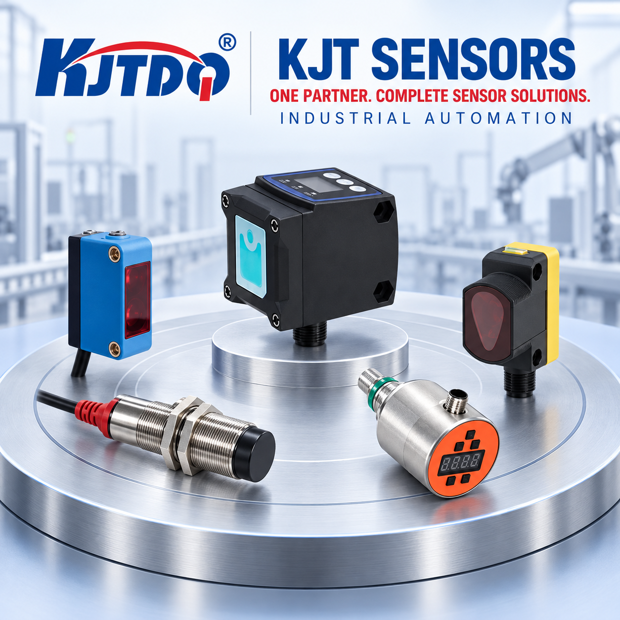
- Laser distance (tracking and positioning). The TLS laser ranging family publishes high-frequency laser ranging displacement sensors in range classes from 1 m to 200 m. The TLS-30C model page publishes 1 mm resolution, accuracy 1.5 mm + 0.5‰, output time ≥4 ms, 5–30 Hz selectable measurement frequency, fast/slow sliding average, Distance-Object switching mode with adjustable hysteresis, PNP/NPN + 0–10 V / 4–20 mA + RS485 Modbus outputs, and laser class 1 (IEC 60825-1) — all manufacturer-stated and model-specific.
- Radar (moving targets in harsh air). KJT Sensors' radar family publishes millisecond-level response and direct speed measurement for moving targets in dust, fog and outdoor conditions (manufacturer-stated; see the radar section of the distance-technology comparison, .
- Related decisions with their own owners. Stacker-crane and rack-location positioning in warehouses is covered by the logistics guide; the laser distance / laser displacement / LiDAR taxonomy is covered by; small-part counting at high line speed is covered by .
Browse the measuring-sensor category or the product center for the full range.
Limitations and Unsuitable Conditions
- All published figures quoted here are manufacturer-stated, model-specific and measured under defined conditions; repeatability for your operating point must be confirmed by data sheet and sample test.
- Optical distance sensors are unsuitable where heavy dust or steam permanently fills the measurement path; radar or contact methods are the fallback.
- Very high-speed event capture (sub-millisecond) exceeds the class of sensors discussed here and requires specialized measurement systems.
- This article covers distance and position measurement on moving targets. Presence-only detection of small fast parts is a photoelectric/fiber-optic decision, and continuous level measurement on moving surfaces is a separate application class.
Frequently Asked Questions
How fast must a distance sensor respond to a moving target? Fast enough that its response time fits well inside the time the target spends in the measurement zone, and its update rate delivers several readings across your tolerance band. Compute the time-in-zone from target speed and zone length first; then compare it against the sensor's published response time and measurement frequency — for example, the TLS-30C publishes output time from ≥4 ms and 5–30 Hz frequency. Verify at maximum line speed by test.
Does target angle affect a laser distance reading? Yes. A tilted target deflects the reflected beam away from the receiver, reducing signal and effective range, and can shift the measured point across the surface. Keep the sensor axis near-perpendicular to the measured surface; where the angle cannot be changed, confirm performance at the actual installation angle by test.
Which output should connect a moving-target sensor to a PLC or controller? Match the output to where the speed decision happens: switching outputs (PNP/NPN, relay) when the sensor itself decides "in position"; analog (0–10 V / 4–20 mA) for continuous position feedback into a fast input; RS485 for digital multi-value data at bus cadence. The TLS-30C publishes all three on one model — confirm the interface's update behavior, not just its presence.
What is the difference between repeatability and accuracy for positioning? Accuracy is closeness to the true distance; repeatability is the spread of repeated readings under identical conditions. Positioning and guidance tasks usually need tight repeatability more than absolute accuracy, because the machine returns to a taught point. Specify both, but acceptance-test the repeatability at your real distance, surface and speed.
Can a laser distance sensor track a glossy or dark moving target? Modern sensors reduce color and gloss influence — the TLS family states detection regardless of color, material or gloss — but dark or mirror-like moving targets still reduce returned signal, especially at speed with no time for averaging. Request a sample test on the real target at real speed before specifying a quantity.
What information should I send a manufacturer for a moving-target application? The ten items in the checklist above: motion profile, time-in-zone, tolerance, range, target properties, spot coverage, mounting, environment, output and decision cadence — plus photos of the installation point. Complete motion data is the single biggest factor in getting a correct first recommendation.
Conclusion
A moving-target distance application is a timing problem wrapped in a positioning problem: the sensor must be fast enough for the motion and repeatable enough for the tolerance, on the real surface, at the real angle, through the real interface. Characterize the motion first, size response and update rate second, specify repeatability third — then prove it with a sample test at maximum line speed.
Ready to specify a moving-target distance sensor? Send KJT Sensors the completed checklist with your motion and target data — the application team will recommend a model and can arrange sample testing. Explore the laser ranging family or start from the product center.
Sources
| # | Source | Type | Used for |
|---|---|---|---|
| 1 | KJT Sensors TLS-30C model page — https://www.kjt-sensors.com/show-559.html (verified 2026-10-10) | KJT Sensors first-party | 1 mm resolution; accuracy 1.5 mm + 0.5‰ (1σ basis noted); output ≥4 ms; 5/10/20/30 Hz; sliding average fast/slow; DtO mode; hysteresis; PNP/NPN + 0–10 V / 4–20 mA + RS485 Modbus; 15×15 mm spot @10 m; laser class 1 IEC 60825-1 (all manufacturer-stated) |
| 2 | KJT Sensors laser ranging family page — https://www.kjt-sensors.com/list-jgcjcgq.html (verified 2026-10-09) | KJT Sensors first-party | TLS range classes 1–200 m; color/material/gloss-independence statement |
| 3 | KJT Sensors radar sensor page — https://www.kjt-sensors.com/list-radar_sensors.html (verified 2026-10-09) | KJT Sensors first-party | Millisecond-level response; speed measurement (manufacturer-stated) |
| 4 | KJT Sensors measuring-sensor category — https://www.kjt-sensors.com/list-clcgq.html (verified 2026-10-10) | KJT Sensors first-party | Measuring portfolio navigation |
| 5 | KJT Sensors product center — https://www.kjt-sensors.com/list-product.html (verified 2026-10-10) | KJT Sensors first-party | Portfolio navigation |
| 6 | KJT Sensors Laser and Measuring Category Knowledge Bases (internal, 2026) | KJT Sensors internal documentation | Selection-recommendation structure; application context |
https://www.kjt-sensors.com/
KJT Sensors