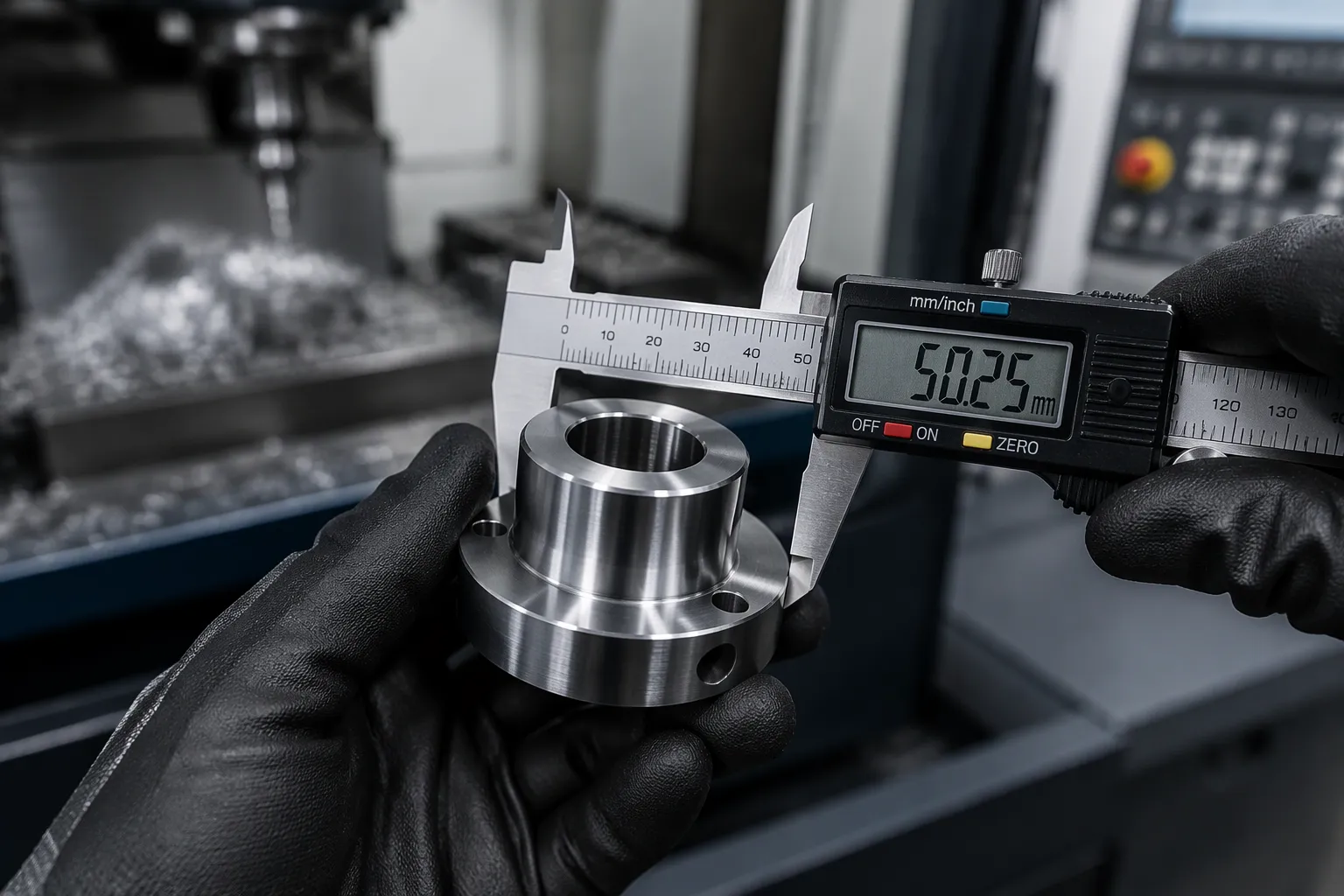
Surface finish and dimensional accuracy are interdependent outcomes of the same machining and finishing decisions. They are not separate specifications to optimize in isolation. Material-removing finishing improves surface texture but can shift dimensions. Non-removing finishing preserves tolerance but may leave tool marks or surface defects. The correct balance is application-specific. Fit, function, sealing, wear, and cost targets drive the choice. Specify both metrics together on the drawing when you write a professional B2B technical article about CNC machined metal parts for American industrial buyers.
Key Takeaways
- Specify surface finish and dimensional tolerance together on the drawing to avoid rework.
- Choose finishing methods that match the part's function and plan for any dimensional changes.
- Use process control and inspection to confirm both surface finish and dimensions on every part.
Key Factors That Affect Surface Finish and Dimensional Accuracy
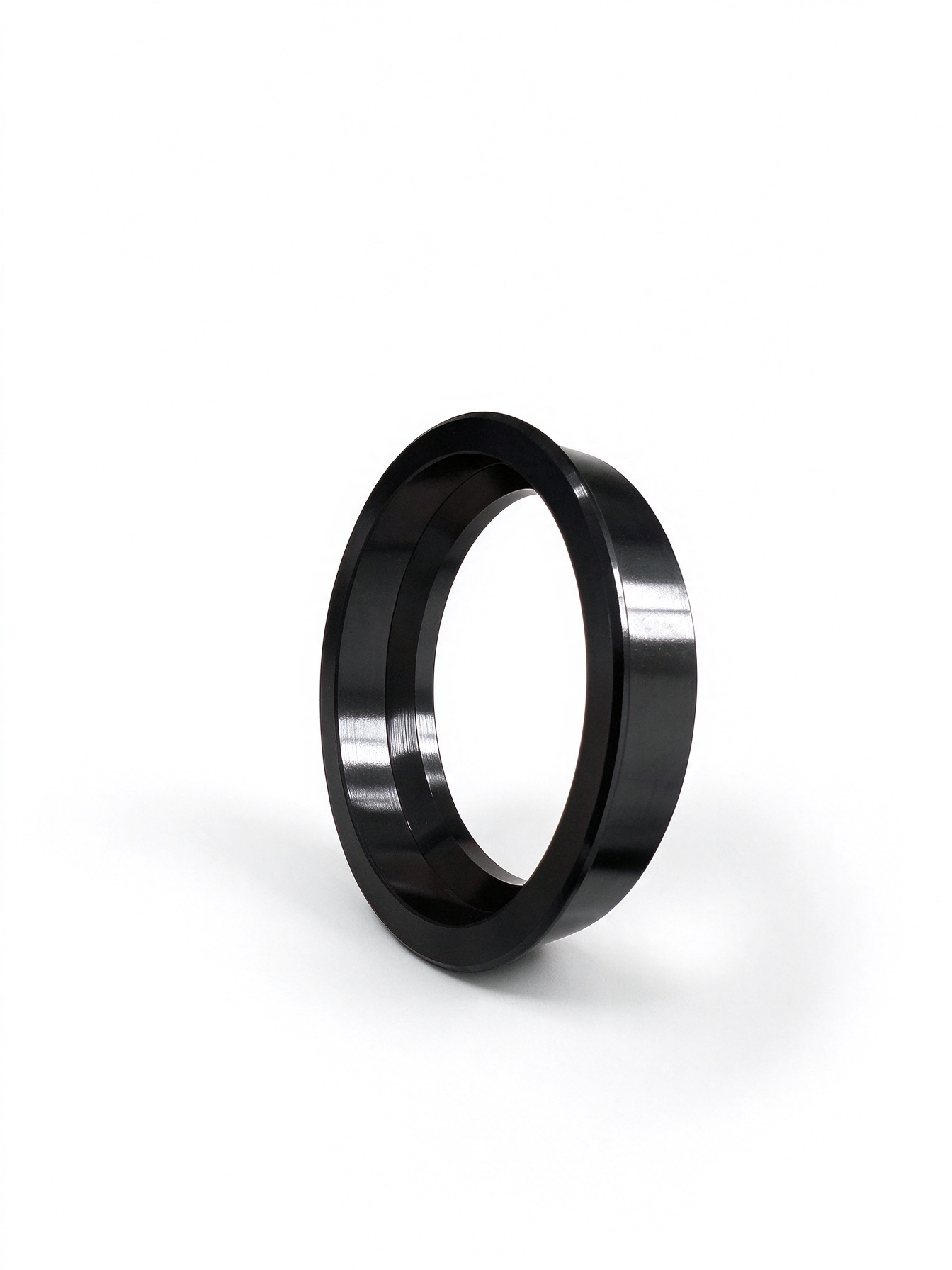
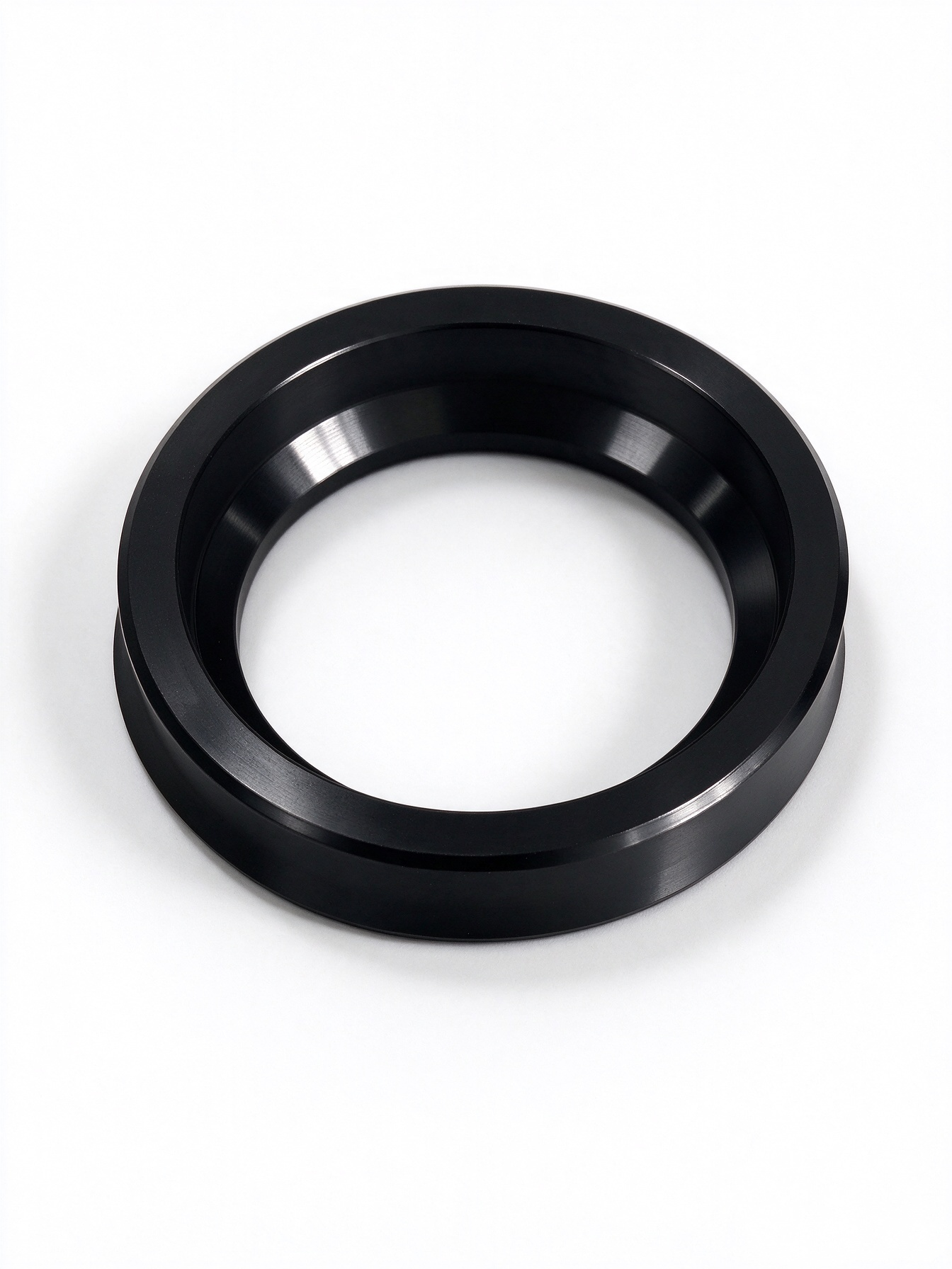
Four variables decide how well a machined metal part meets both specifications. Each one shifts the achievable balance between texture and tolerance.
Material Properties
Material behavior sets the starting point for both metrics. Aluminum cuts freely and accepts fine finishes, yet it moves under clamping and thermal load. Stainless steel work-hardens and generates heat at the cutting edge. Cast iron and ductile iron release graphite dust and carry residual stress from the blank. Hardness, thermal conductivity, and stress condition all influence how much material a finishing pass can remove without disturbing dimensions.
Part Geometry and Feature Size
Thin walls, deep pockets, and long slender shafts deflect under cutting force. Deflection shows up twice: as chatter marks on the surface and as dimensional drift across the feature. Small holes and narrow slots limit tool access and restrict chip evacuation. A stable workholding plan with a shared datum and sequenced passes controls both effects at once.
Tooling and Machine Capability
Tool geometry, coating, and machine rigidity define the practical window for finish and tolerance. Sharp tooling with the correct nose radius produces a cleaner surface at a given feed rate. A rigid setup holds size across a production run.
| Factor | Effect on Finish | Effect on Accuracy |
|---|---|---|
| Tool nose radius and coating | Controls scallop height and wear | Affects size hold over tool life |
| Machine rigidity | Reduces chatter and vibration marks | Limits achievable tolerance band |
| Fixture and datum strategy | Stabilizes surface contact | Prevents set-up stacking error |
Budget and Production Volume
Finishing cost scales with operations, not with part weight. A single prototype can justify hand polishing or selective inspection. A medium batch rewards process control, in-process gauging, and finishing methods with predictable dimensional allowance. Volume also determines whether outsourced operations such as plating or anodizing earn their lead time.
Surface Finish Methods and Their Dimensional Impact

Finishing methods fall into two families. Mechanical methods remove material and change the surface profile. Chemical and electrochemical methods add a layer or convert the surface without cutting. Each family carries a different dimensional signature. A buyer who understands that signature can specify finish and tolerance as one requirement instead of two.
Mechanical Finishing Methods
Mechanical finishing cuts, hones, or burnishes the surface. Every pass removes a small amount of material. The removal improves texture and reduces tool marks. The same removal changes the final size of the feature.
Grinding uses an abrasive wheel to correct size and finish together. A controlled grinding pass can hold a tolerance band while producing a fine surface. The operator must plan the stock allowance before grinding. Too little stock leaves tool marks. Too much stock extends cycle time and adds heat.
Honing refines the bore of a cylinder or sleeve. The abrasive stones follow the existing axis. Honing improves roundness and surface texture without changing the centerline. Cross-hatch pattern control supports oil retention on sliding surfaces.
Lapping produces a very fine flat or cylindrical surface. The process removes material in micron increments. Lapping suits sealing faces, gauge surfaces, and precision mating parts. Dimensional change is small and predictable when the allowance is set at the drawing stage.
Polishing and buffing improve appearance and lower surface roughness. These operations remove material unevenly on complex geometry. A polished cosmetic face may lose edge definition on sharp corners. Specify a maximum edge break and a surface roughness value together.
Sandblasting and brushing create a uniform texture rather than a mirror surface. Blasting peens the surface and can close small pores. Brushing sets a directional grain. Both methods change the surface appearance and leave the base dimension essentially intact. Masking protects critical fits and threaded features during blasting.
| Mechanical Method | Material Removal | Dimensional Effect | Typical Fit |
|---|---|---|---|
| Grinding | Low, controlled | Corrects size within a planned allowance | Bearing seats, shafts |
| Honing | Very low | Improves roundness, holds centerline | Cylinder bores, sleeves |
| Lapping | Micron level | Fine size correction on flat or round faces | Sealing faces, gauges |
| Polishing and buffing | Uneven, low | Can soften edges and corner definition | Cosmetic and decorative faces |
| Sandblasting and brushing | Negligible | Texture change with minimal size shift | Pre-coating prep, appearance |
Mechanical methods reward early planning. The machining drawing should state the finishing allowance, the final surface roughness, and the protected features. A part designed with that allowance reaches final size after finishing, not before.
Chemical and Electrochemical Methods
Chemical and electrochemical methods do not cut the surface with a tool. They grow a film, convert the base metal, or deposit a metal layer. The dimensional impact comes from coating thickness and from the nature of the conversion.
Anodizing grows an oxide film on aluminum. Type II anodizing builds a film of roughly 10 to 20 μm. The film grows both outward and into the base metal. A machined dimension therefore changes after coating. Type III hard anodizing builds a thicker film of 25 to 50 μm for wear surfaces. The coating growth must be factored into the machining dimension so the finished size lands inside tolerance.
Chemical conversion coating replaces a thin surface layer on aluminum or stainless steel. The film is thin and does not change functional dimensions in a meaningful way. Class 3 low-resistance coating serves grounding and electrical contact surfaces. The process preserves the machined size and adds corrosion protection.
Zinc plating deposits a sacrificial layer on carbon steel. The layer thickness is agreed per order and tied to salt spray performance. Threaded features need allowance for coating buildup. Internal threads and close-clearance holes are the usual watch points.
Electroless and electrolytic nickel deposits a functional layer on steel and copper alloys. Electroless nickel builds a uniform thickness across complex geometry. Electrolytic nickel offers a different property set and a different thickness profile. Both require a pre-plate dimension that accounts for the deposit.
Black oxide converts the surface of carbon steel into a dark film. The dimensional change is negligible. The finish provides low reflection and requires an oil film for corrosion protection. It suits tooling and optical structures where size control matters more than coating build.
| Chemical or Electrochemical Method | Build or Conversion | Dimensional Impact | Planning Action |
|---|---|---|---|
| Type II anodizing | Oxide growth, 10–20 μm | Size grows after coating | Set pre-coat dimension below final size |
| Type III hard anodizing | Oxide growth, 25–50 μm | Larger growth on wear surfaces | Plan allowance in the machining drawing |
| Conversion coating | Thin conversion film | Minimal size change | Protect conductive contact areas |
| Zinc plating | Sacrificial deposit | Buildup on threads and holes | Allow for coating on mating features |
| Nickel plating | Metal deposit | Uniform or profiled buildup | Define pre-plate size and thickness |
| Black oxide | Surface conversion | Negligible size change | Control oil film and storage condition |
These methods protect the surface without disturbing the machined profile in most cases. The exceptions are the coating methods with real build. Anodizing and plating belong on the drawing as a dimensioned requirement, not as a note added after machining.
Selecting the Right Method for Your Application
Method selection starts with the function of the surface. A sealing face needs low roughness and flatness. A wear surface needs hardness and a controlled film. A grounding interface needs low electrical resistance. An outdoor housing needs corrosion resistance and color consistency. Each function points to a small set of methods.
The tolerance class narrows the choice further. A tight tolerance on a coated part demands allowance planning before the first cut. A tight tolerance on an uncoated part favors a method with negligible build. A loose tolerance opens the door to methods with more dimensional variation.
Material compatibility removes options that do not fit. Aluminum accepts anodizing and conversion coating. Carbon steel accepts zinc plating and black oxide. Stainless steel accepts passivation and conversion coating. Copper alloys accept nickel plating. A method that does not suit the base metal will fail in service regardless of the surface number.
Production volume shapes the economics. Prototype quantities can absorb hand polishing and selective inspection. Medium batches reward methods with predictable allowance and stable process control. Outsourced operations such as plating and anodizing add lead time and need a separate scheduling window.
Specify the finish method, the surface roughness value, and the dimensional allowance on the same drawing. A finish note without an allowance is an incomplete requirement.
When you write a professional B2B technical article about CNC machined metal parts for American industrial buyers, the selection logic above is the practical core. The method must serve fit, function, and cost at the same time. A finish chosen for appearance alone can break a tolerance. A tolerance chosen without regard to coating build can break the finish. The two decisions belong together.
A final check ties the method to verification. The inspection plan should confirm the surface roughness and the final dimension after finishing. Coating thickness, adhesion, and salt spray records close the loop for protective finishes. That documentation gives the buyer a complete picture of the delivered part.
Optimizing Dimensional Accuracy Alongside Surface Finish
Surface finish and dimensional accuracy move together through every stage of production. A finishing pass that improves texture can shift a critical dimension. A machining strategy that holds size can leave a surface that fails a sealing requirement. The sections below cover the three controls that keep both metrics inside specification: tolerance management, process control, and inspection.
Tolerance Management and Design Intent
Tolerance management starts with design intent. Every dimension on the drawing should trace back to a function. A bearing seat needs a tight size and a fine surface. A clearance hole needs position control and a moderate surface. A cosmetic face needs appearance control and a loose size. When the drawing ties each tolerance to a function, the shop can plan machining and finishing as one sequence.
A common failure mode is tolerance stacking. Each operation adds a small error. Rough machining, semi-finish machining, heat treatment, finish machining, and coating all contribute. The final dimension carries the sum of those errors. A drawing that assigns tight tolerances to every feature leaves no room for the finishing allowance. A drawing that reserves tight tolerances for functional features gives the shop room to plan.
Design intent also sets the datum scheme. A shared datum across set-ups prevents alignment drift. A part machined in one set-up with a turn-mill operation avoids the stacking error that comes from reclamping. The datum choice belongs on the drawing, not in the shop's discretion. When the datum is explicit, the inspection plan can reference the same features.
| Design Intent | Tolerance Strategy | Finishing Strategy |
|---|---|---|
| Bearing or sealing fit | Tight size and roundness | Fine surface with planned allowance |
| Clearance or locating hole | Position control, moderate size | Standard machined surface |
| Cosmetic or visible face | Loose size, appearance control | Texture and color matched to sample |
| Coated wear surface | Pre-coat dimension with build allowance | Coating thickness specified on drawing |
Tolerance management also covers the default tolerance block. Unspecified tolerances should follow a recognized standard, such as ISO 2768-1 class m. A clear default removes ambiguity on non-critical features. Critical features then carry explicit tolerances. This split keeps the drawing readable and keeps cost focused on the features that matter.
A tolerance without a stated function invites over-machining. A function without a stated tolerance invites assembly failure.
The design intent review is the right moment to catch conflicts. A tight flatness call on a face that will be sandblasted may not survive the blasting. A tight bore tolerance on a part that will be anodized needs a pre-coat dimension. Reviewing finish and tolerance together at the drawing stage prevents rework later.
Process Control and Machining Parameters
Process control converts a good drawing into a repeatable part. The machining parameters set the surface texture and the dimensional result at the same time. Feed rate, cutting speed, depth of cut, and tool path strategy all influence both outputs.
Feed rate has a direct effect on surface roughness. A lower feed per tooth reduces the scallop height and improves the surface. The same lower feed can increase cycle time and heat input. Heat input causes thermal growth and dimensional drift on long runs. The shop must balance texture against thermal stability.
Cutting speed affects tool wear and surface quality. A worn tool raises cutting force and leaves a rougher surface. Tool wear also changes the effective tool size and shifts the dimension. A tool life management plan replaces tools before wear reaches the point where size drifts. In-process gauging confirms the size trend and triggers a tool change.
Depth of cut controls the finishing allowance. A light finish pass removes the tool marks from the roughing pass and sets the final surface. The finish pass must leave enough stock to clean up the surface without removing so much that the dimension moves. A planned allowance on the drawing makes this pass predictable.
| Parameter | Effect on Surface Finish | Effect on Dimensional Accuracy |
|---|---|---|
| Feed per tooth | Lower feed improves texture | Lower feed adds heat and cycle time |
| Cutting speed | Correct speed limits wear marks | Worn tools shift size |
| Depth of finish cut | Cleans up roughing marks | Sets final size within allowance |
| Coolant strategy | Flushes chips, limits smearing | Controls thermal growth |
Workholding and clamping force belong in the process control plan. Excessive clamping force distorts thin walls. The part springs back after unclamping and the dimension moves. Sequenced passes with stress release reduce this effect. A shared datum and stable fixture keep the part in the same position across operations.
Thermal control matters on tight-tolerance work. The shop floor temperature, the coolant temperature, and the heat from cutting all affect the final size. A warm part measures differently from a cold part. A stabilization period before final inspection removes this variable. The measurement temperature should match the drawing reference temperature.
Process control also covers the finishing sequence. A part that will be coated needs the pre-coat dimension set below the final size. A part that will be ground needs the grinding allowance left on the surface. The sequence of machining, finishing, and inspection should be written into the process plan. Each step confirms the state of the part before the next step begins.
Inspection and Verification
Inspection closes the loop between the drawing and the delivered part. The inspection plan should confirm both the surface finish and the dimensional result. A part that passes one check and fails the other is not a conforming part.
Dimensional measurement uses the tools that match the tolerance band. Calipers and micrometers cover general dimensions. Bore gauges and pin gauges cover hole sizes. A coordinate measuring machine covers position, profile, and geometric tolerances. The measurement tool must have resolution fine enough for the tolerance. A tolerance of ±0.01 mm needs a tool that reads well below that band.
Surface inspection uses roughness measurement and visual comparison. A surface roughness tester reports the Ra value against the drawing requirement. A visual comparison against an approved sample confirms appearance, brush direction, and grain depth. Both checks belong in the inspection record.
| Inspection Check | Method | Record |
|---|---|---|
| Critical dimensions | Micrometer, bore gauge, CMM | Dimensional report |
| Surface roughness | Roughness tester | Ra value against drawing |
| Coating thickness | Coating thickness gauge | Thickness record |
| Appearance | Visual against approved sample | Appearance sign-off |
| Corrosion performance | Salt spray test | Salt spray record |
First article inspection verifies the process before production release. The first article confirms that the machining and finishing sequence produces a conforming part. A full dimensional report documents every drawing requirement. Any deviation is caught before the run continues.
In-process inspection keeps the run stable. Sampling at set intervals catches tool wear and process drift. The sample size and frequency should match the tolerance tightness and the production volume. A tight-tolerance feature needs more frequent checks than a general dimension.
Final inspection confirms the delivered part. The inspection documents travel with the shipment. Material test certificates, dimensional reports, first article inspection reports, salt spray records, and PPAP packages give the buyer a complete quality record. These documents support the buyer's own incoming inspection and their end-customer requirements.
When you write a professional B2B technical article about CNC machined metal parts for American industrial buyers, the inspection section is where trust is built. A supplier that documents both surface finish and dimensional results gives the buyer a verifiable part. A supplier that documents only one metric leaves a gap.
Verification also covers the finishing suppliers. Outsourced plating, anodizing, and EDM carry their own quality risk. The machining supplier should retain responsibility for those operations and confirm the results. Coating thickness, adhesion, and salt spray records should be collected and reviewed before shipment. This step keeps the delivered part consistent with the drawing, regardless of which operation produced the final surface.
Balancing Cost, Lead Time, and Performance
Cost, lead time, and performance pull against each other on every machined part. Tight tolerances and fine finishes raise cost and extend lead time. The right question is where those tighter specifications earn their keep.
Where Tight Tolerances and Fine Finishes Pay Off
Tight specifications pay off when a feature carries a real function. A bearing seat, a sealing face, or a hydraulic bore justifies a fine surface and a close tolerance. A failure at these features stops the machine or leaks the system. The added machining and inspection cost protects a much larger investment.
| Application | Specification Driver | Justified Investment |
|---|---|---|
| Bearing and shaft fits | Roundness, size, surface texture | Fine turning or grinding, CMM checks |
| Sealing faces | Flatness, low Ra | Lapping, roughness testing |
| Hydraulic bores | Roundness, cross-hatch | Honing, bore gauging |
| Grounding contacts | Low electrical resistance | Class 3 conversion coating |
| Cosmetic housings | Appearance consistency | Sample-matched texture and color |
Loose specifications suit clearance holes, non-critical brackets, and internal features with no mating contact. Standard machining and default tolerances serve these features well. Spending tight tolerances here adds cost without adding function.
Cost-Effective Specification Practices
Cost-effective specification starts with function-based tolerances. Assign tight tolerances only to features that need them. Let the default tolerance block, such as ISO 2768-1 class m, cover the rest. This split concentrates cost where it protects performance.
A second practice is to specify finish and tolerance as one requirement. State the Ra value, the coating allowance, and the final dimension together. This prevents rework caused by a finish note added after machining.
Early supplier collaboration controls cost and lead time. A machining partner can review the drawing before release and flag conflicts. The partner can confirm achievable tolerances, finishing allowances, and realistic delivery dates. This review costs little at the quotation stage and saves much more after production starts.
Write a Professional B2B Technical Article About CNC Machined Metal Parts for American Industrial Buyers
Specifying Finish and Tolerance Together on the Drawing
A drawing that states finish and tolerance as one requirement removes ambiguity at the quotation stage. Place the surface roughness value, the coating allowance, and the final dimension in the same feature callout. A bore that will be hard anodized needs a pre-coat dimension below the final size. A sealing face needs a flatness call and an Ra value side by side. Default tolerances should follow a recognized standard, such as ISO 2768-1 class m, so critical features carry explicit values and non-critical features stay economical. Metric and inch drawings both work when the units and the standard are stated once, clearly.
Qualifying a Machining Partner for Both Metrics
Qualification tests two capabilities at once: size control and surface control. Ask for a first article inspection report that lists every drawing requirement, including Ra values and coating thickness. Request material test certificates to EN 10204 3.1, dimensional reports, salt spray records, and a PPAP package where the program requires one. Confirm the partner holds responsibility for outsourced finishing, so plating and anodizing results stay inside the same quality record. A partner who documents both metrics gives the buyer a verifiable part and a clean incoming inspection.
Surface finish and dimensional accuracy belong together on the drawing. Tie Ra values and tolerances to real functional requirements. Validate material, geometry, tooling, and finishing choices through process control and inspection records. Engage your machining supplier early to align specifications, cost, and lead time before release. Write a professional B2B technical article about CNC machined metal parts for American industrial buyers with this principle at its center. Contact Qingdao Xuxiangtai Machinery to review your part specifications and optimize finish and accuracy for your application.
FAQ
Should surface finish and tolerance appear on the same drawing callout?
Yes. State the Ra value, the coating allowance, and the final dimension together. This pairing prevents rework. A finish note added after machining often breaks a critical tolerance.
How does coating build affect a tight tolerance?
Anodizing and plating add a measurable layer. Plan the pre-coat dimension below the final size. Type III hard anodizing builds 25 to 50 μm, so the allowance belongs in the machining drawing.
What documents prove both metrics on delivered parts?
Request a first article inspection report, a dimensional report, and roughness readings against the drawing. Material certificates to EN 10204 3.1 and salt spray records complete the quality package.
See Also
Avoid Making Incorrect Aluminum Casting Process Decisions Ever Again
https://www.xuxiangtaimetal.com
Qingdao Xuxiangtai Machinery