As factories, commercial buildings, data centers, transportation facilities, and other power-intensive sites become increasingly electrified, electrical distribution systems must handle higher loads while remaining compact, reliable, flexible, and easy to maintain.
Traditional cable distribution remains a practical solution for many installations. However, large numbers of cables can create challenges when a project requires high current capacity, dense equipment layouts, frequent load changes, or limited installation space.
A sandwich busway system provides an alternative approach. By arranging conductive busbars and insulation within a compact enclosure, a busway can create an organized route for transmitting and distributing electrical power between the main supply and downstream loads.
For facilities where power demand is high and future expansion is expected, a properly engineered busway system can become an important part of the overall electrical infrastructure.
What Is a Sandwich Busway System?
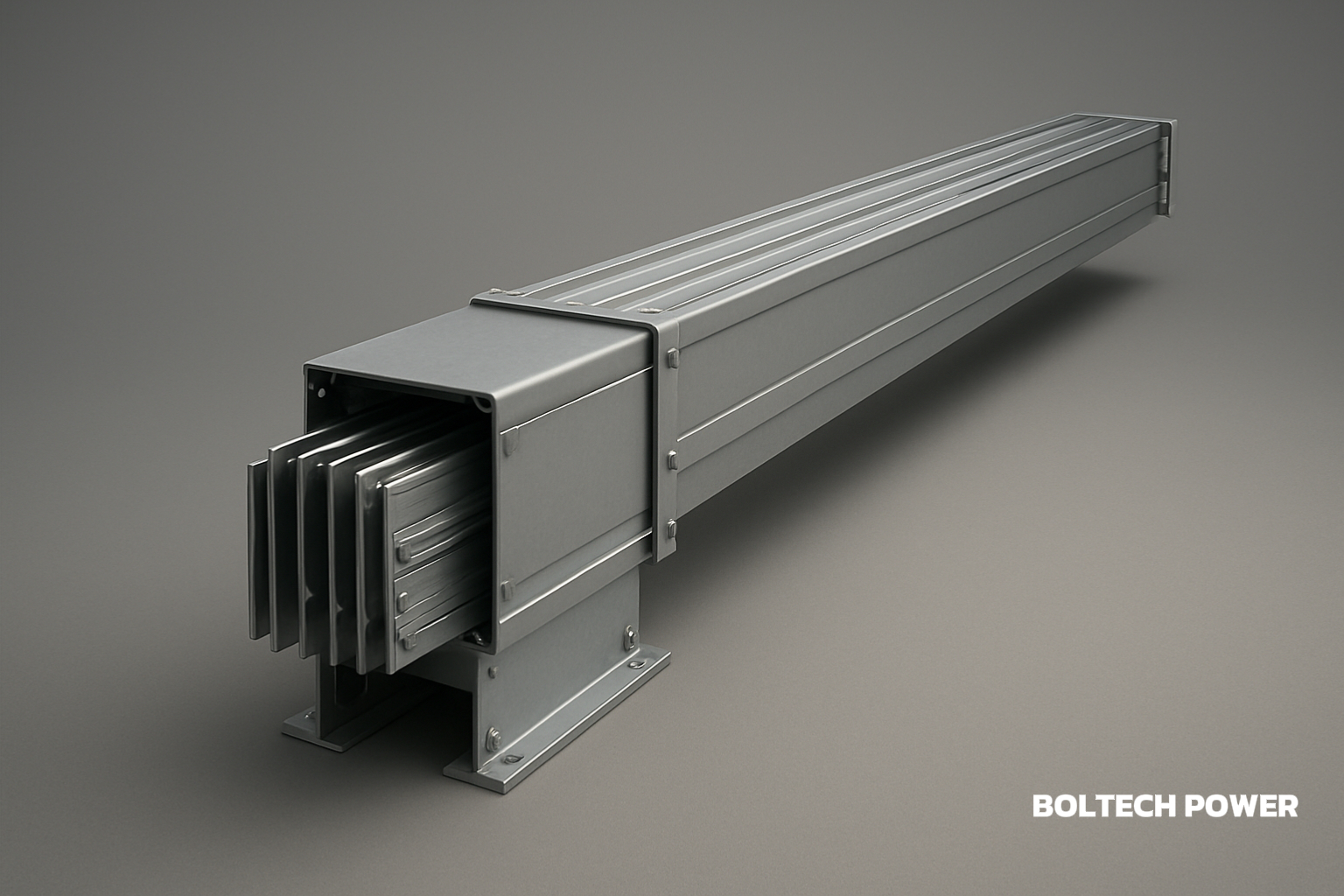
A sandwich busway system is a power distribution assembly in which conductive bars are positioned closely together and separated by insulating materials inside a protective enclosure.
This differs from conventional cable distribution, where individual conductors are routed separately and typically require cable trays, supports, bending space, and additional installation clearance.
The compact "sandwich" arrangement allows the conductors and insulation to form a relatively dense distribution structure. Depending on the project, busway products can be configured for different distribution requirements, including intensive busway, feeder busway, and plug-in busway applications.
The appropriate configuration depends on factors such as rated current, load locations, installation direction, connection requirements, environmental conditions, and future expansion plans.
Compact Distribution for High-Density Electrical Environments
One of the most practical reasons to consider busway is space utilization.
As electrical loads increase, cable routes can become crowded. A large cable installation may require extensive support systems and dedicated cable management space, particularly when several circuits need to run between different areas of a facility.
A compact busway route can help organize power distribution within a smaller installation envelope.
This can be useful for:
-
Manufacturing plants
-
Data centers
-
Commercial buildings
-
Warehouses
-
Hospitals
-
Transportation facilities
-
Industrial parks
-
Large infrastructure projects
In multi-story buildings, busway can also be used for vertical power distribution, while horizontal sections can serve production areas or equipment zones.
The actual space savings depend on the system design, installation requirements, and comparison with the alternative cable arrangement.
How Busway Can Support Efficient Power Transmission
Electrical distribution efficiency depends on conductor resistance, route length, load characteristics, connection quality, and system design.
A busway system provides a structured conductive path that can be engineered around the required current and distribution route. Its compact conductor arrangement can help reduce unnecessary conductor routing and make the overall distribution network more organized.
This becomes increasingly relevant in facilities that operate large electrical loads for long periods.
Manufacturing plants may simultaneously power motors, pumps, compressors, HVAC equipment, production machinery, and lighting. Data centers may operate servers, cooling equipment, UPS systems, and auxiliary loads continuously.
When electrical demand is high, even relatively small distribution losses can become significant over time. Proper conductor sizing, appropriate busway selection, efficient routing, and good connection design are therefore essential.
A busway system should not be viewed as an automatic energy-saving solution. Its efficiency depends on correct engineering and installation.
Faster and More Organized Installation
Large electrical projects can require substantial labor for cable installation.
Traditional cable distribution may involve pulling cables, routing them through trays, installing supports, making terminations, labeling circuits, and performing testing. As the number of circuits increases, installation complexity can grow rapidly.
Busway systems use modular sections that can be assembled along predetermined routes. Straight sections, connection components, joints, and other accessories can be arranged according to the building or factory layout.
This modular approach can make installation more systematic and easier to plan.
It can also be useful during future modifications. If production equipment is relocated or a new electrical area is added, engineers can assess whether additional busway sections or connection points can be integrated instead of redesigning an entire cable network.
Flexibility for Changing Electrical Loads
Modern facilities rarely maintain exactly the same equipment configuration throughout their entire service life.
A manufacturing plant may add new production lines. A warehouse may install automated material-handling systems. A commercial building may change tenants. A data center may increase equipment density.
These changes can increase or relocate electrical loads.
Plug-in busway systems can provide designated connection locations where compatible electrical loads can be connected according to the system design. This modular structure can make certain modifications more manageable than installing new long cable routes.
For facilities with frequently changing layouts, this flexibility can be an important consideration during initial electrical planning.
However, future expansion should be considered before installation. Engineers need to evaluate spare capacity, connection locations, protection requirements, and available physical space rather than assuming that every busway can be expanded indefinitely.
Electrical Safety Requires Complete System Engineering
A busway system can provide a more organized distribution structure, but it is not a substitute for proper electrical engineering.
System safety depends on multiple factors, including:
-
Correct current rating
-
Insulation performance
-
Enclosure design
-
Grounding
-
Short-circuit withstand capability
-
Protection coordination
-
Connection quality
-
Environmental conditions
-
Installation workmanship
-
Inspection and maintenance
For critical facilities such as hospitals, airports, rail infrastructure, industrial plants, and data centers, these factors need to be evaluated as part of the complete power distribution system.
The busway must also be coordinated with upstream and downstream equipment to ensure that the overall system operates within its design limits.
Maintenance and Troubleshooting Considerations
Long-term maintainability should be considered during electrical system design.
Complex cable networks can become difficult to inspect when large numbers of cables occupy crowded trays or shafts. Identifying a particular circuit or modifying a route may require significant preparation.
A modular busway arrangement can provide a more structured distribution layout. Standardized sections and connection points can make it easier for maintenance personnel to identify different parts of the power route.
Clear labeling and accurate electrical documentation remain essential, regardless of the distribution method.
Maintenance teams should also have appropriate access for inspection, testing, and servicing. The installation environment, operating temperature, dust levels, moisture exposure, and expected load should be considered when establishing maintenance procedures.
How to Select the Right Sandwich Busway System
Choosing a busway system should begin with the actual electrical requirements of the project rather than the product name alone.
Key parameters include:
Rated Current
Determine the continuous electrical load and consider reasonable capacity for expected future expansion.
Short-Circuit Requirements
The system should be evaluated according to the prospective short-circuit conditions and required withstand capability.
Installation Environment
Indoor and outdoor installations may have different requirements for enclosure protection, temperature, humidity, dust, and ventilation.
Distribution Direction
The design may involve horizontal routes, vertical risers, or a combination of both.
Connection Requirements
The number and location of downstream loads should be mapped before finalizing the busway layout.
Insulation and Grounding
The insulation system and grounding arrangement must be compatible with the project's electrical design and applicable standards.
Future Expansion
Engineers should consider whether additional loads, connection points, or production areas are likely to be added later.
A properly sized system can provide better long-term flexibility than one designed only around today's electrical demand.
Integrating Busway Into a Complete Power System
Busway should not be designed as an isolated component. It forms part of a larger electrical distribution architecture.
For example, a large industrial facility may combine:
Generator → Switchgear → Automatic Transfer Equipment → Busway → Distribution Panels → Electrical Loads
Each stage has a different function, but all components must operate together.
Boltech has more than 37 years of experience in the power equipment industry and provides diesel generator sets and related electrical system solutions for industrial, commercial, and infrastructure applications. Its generator products cover power ranges from 3 kW to 5000 kW, with engineering services covering system design, equipment supply, installation, commissioning, and maintenance.
This broader system experience can be useful when integrating busway with generators, switchgear, transfer systems, distribution panels, and downstream loads.
For example, in a factory, generator sets may provide backup power while switchgear manages incoming and outgoing circuits and busway distributes electricity to production areas and high-power equipment.
The final configuration should be based on the facility's actual load profile, equipment arrangement, operating environment, and backup power requirements.
When Is a Sandwich Busway System a Practical Choice?
A busway system can be particularly useful when a project combines high electrical loads with dense equipment layouts and a need for future flexibility.
It may be considered for:
-
Large manufacturing facilities
-
Data centers with high equipment density
-
Commercial complexes
-
High-rise building power risers
-
Transportation infrastructure
-
Hospitals
-
Warehouses
-
Industrial parks
-
Infrastructure projects with substantial electrical loads
The suitability of busway still depends on the project's electrical architecture, installation environment, applicable standards, and cost considerations.
Conclusion
A sandwich busway system provides a compact and modular approach to electrical power distribution. Compared with complex cable-based installations, it can offer practical advantages in space utilization, installation organization, load connection, maintenance access, and future modification.
These characteristics make busway technology relevant to modern factories, data centers, commercial buildings, transportation facilities, hospitals, and other high-power environments.
However, successful implementation depends on proper system engineering. Rated current, short-circuit withstand capability, insulation, grounding, protection coordination, environmental conditions, installation layout, and future load growth should all be evaluated before selecting the system.
For projects that require reliable and flexible electrical distribution, integrating a properly designed sandwich busway system with generators, switchgear, transfer equipment, distribution panels, and end-use loads can provide a structured foundation for long-term power management.
www.boltechpower.com
BOLTECH Power Equipment