In power electronics, a transformer’s performance is only as stable as the parts that hold it together. While engineers spend most of their time on magnetic core selection and winding design, the multi-pin transformer bobbin frame is what keeps winding geometry, insulation spacing, and terminal alignment consistent from prototype to mass production.
If you’re building EV chargers, OBC power modules, telecom power supplies, industrial converters, or any high-density PCB assembly, multi-pin frames are often the best choice because they simplify routing and improve assembly repeatability.
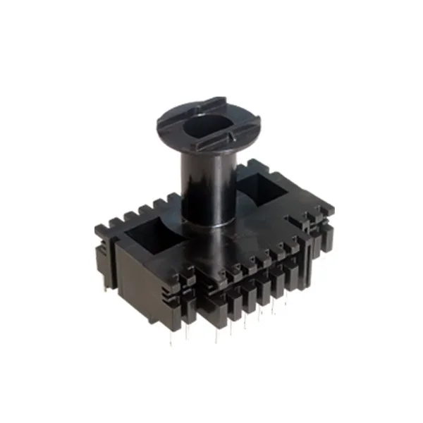
For a product reference and capability overview, you can also view:
Multi-Pin Transformer Bobbin Frame
What is a multi-pin transformer bobbin frame?
A multi-pin transformer bobbin frame is an injection molded coil support structure with multiple terminal pins (often arranged in high-density layouts). It typically integrates:
-
Winding support surfaces (winding window + flanges)
-
Insulation isolation features (partitions or barriers)
-
Terminal pin positioning (pin pitch and datum alignment)
-
Mechanical fixing interfaces (seat planes, guides, locks)
Compared with simple bobbins, multi-pin frames are designed to keep PCB connections clean and predictable—especially when the transformer serves as a power conversion or signal isolation component.
Why multi-pin frames are used in modern power assemblies
1) Cleaner PCB routing and terminal organization
As converters and chargers become more compact, pin count increases. A multi-pin frame helps designers:
-
route primary/secondary terminals more clearly
-
separate groups of leads for isolation design
-
reduce wiring complexity during assembly
2) Better repeatability in mass production
For volume programs, yield is often impacted by small shifts in:
-
pin pitch
-
seating flatness
-
winding window size
A stable multi-pin frame reduces tolerance stacking and helps your assembly line run more consistently.
3) Easier automation
Many factories use semi-auto or fully automated winding and insertion. Multi-pin frames can be optimized for:
-
stable handling points
-
consistent lead lengths and positions
-
reduced rework from misaligned terminals
Key design elements that affect performance
Pin layout and datum control
Pin geometry is usually the first critical feature buyers care about, because it affects:
-
PCB insertion fit
-
soldering quality
-
connector reliability
A well-designed multi-pin frame defines clear reference datums so measurement and production control are consistent.
Winding window geometry
The winding window controls coil build quality. If it drifts, you may see:
-
uneven winding tension
-
coil rubbing on flanges
-
difficulty hitting target turns count within space constraints
Insulation barriers and partitions
In many applications, the bobbin frame also supports insulation strategy by separating:
-
primary vs secondary sections
-
multiple secondary outputs
-
high-voltage vs low-voltage areas
Barrier consistency matters because small variations can create assembly interference or reduce effective isolation space.
Burr-free, wire-safe edges
Winding wire is sensitive to sharp edges. Even small burrs can cause:
-
enamel damage
-
insulation reliability issues
-
inconsistent winding yield
This is why experienced manufacturers pay attention to parting line planning, flash control, and edge finishing standards.
Manufacturing process: what a good supplier should control
A multi-pin transformer bobbin frame looks simple, but stable production relies on several “non-obvious” controls.
1) DFM review before tooling
A strong supplier will review the 2D/3D files and propose changes to reduce:
-
warpage risk on tall flanges
-
stress concentration near pins and partitions
-
flash risk on winding surfaces
-
tolerance over-specification that increases scrap rate
2) Mold design that supports repeatability
Key tooling topics that influence stability:
-
gate strategy and flow balance (affects warpage direction)
-
cooling layout (most important warpage lever)
-
venting (prevents short shots and weak knit lines)
-
ejection plan (prevents bending or stress marks around pin areas)
3) Stable injection molding process window
For multi-pin frames, consistency comes from controlling:
-
mold temperature
-
packing/holding profile
-
cooling time
-
resin drying/handling (material dependent)
A supplier with real process discipline will be able to explain how they lock parameters and monitor drift across long runs.
Common problems and how to prevent them
Pin misalignment
Symptoms: difficult insertion, soldering stress, variable pin spacing
Root causes: warpage, poor datums, unstable process window, mold wear
Prevention: tooling datum strategy, cooling balance, in-process gauging, cavity tracking
Warpage (leaning flanges or twisted frames)
Symptoms: assembly interference, inconsistent winding window geometry
Root causes: uneven wall thickness, unbalanced cooling, wrong gate placement
Prevention: DFM wall-thickness strategy, mold cooling optimization, fixture checks
Flash on winding edges
Symptoms: wire damage, assembly interference
Root causes: parting line wear, clamp issues, poor venting
Prevention: mold maintenance, flash acceptance limits, parting line planning
Cracks at partitions or pin bosses
Symptoms: failures after handling or thermal cycling
Root causes: sharp corners, internal stress from overpacking, brittle grade mismatch
Prevention: corner radii, stress-reduction process tuning, correct resin selection
Sourcing checklist: what to include in your RFQ
If you want quotes that are accurate and comparable, send:
-
2D drawing + 3D STEP file
-
application environment (temperature range and end-use)
-
key “critical-to-function” dimensions marked